If you are looking for Programmable Logic Controllers: The Evolution of a Disruptive you've came to the right web. We have 35 Pictures about Programmable Logic Controllers: The Evolution of a Disruptive like Ladder Diagrams - RoboticsUp, Solved: Write A Program For The Relay Ladder Diagram Shown... | Chegg.com and also Ladder Logic Wiring Diagrams - Wiring Diagram. Here it is:
Programmable Logic Controllers: The Evolution Of A Disruptive
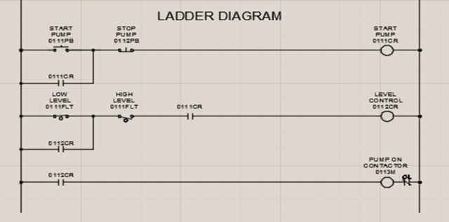 www.engineering.com
 ladder diagram logic relay control circuit diagrams schematic programmable popularity representation gained early days plc engineering intuitive automation simplicity because
What Is Relay Logic ? | Compare Ladder Logic And Relay Logic
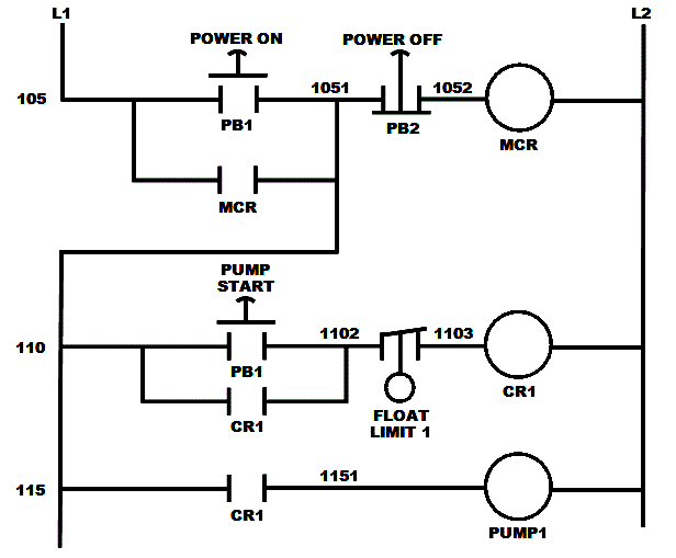 instrumentationtools.com
 logic ladder diagram relay example electrical control circuit compare schematic figure
Modernizing An Old Hardwired Relay Logic With Modern PLC System | EEP
relay electrical logic diagram circuit electromechanical ladder plc engineering wiring symbols relays system hardwired portal old modernizing electronics eep contactor
Relays In Ladder Logic Tutorials | Instrumentation Tools
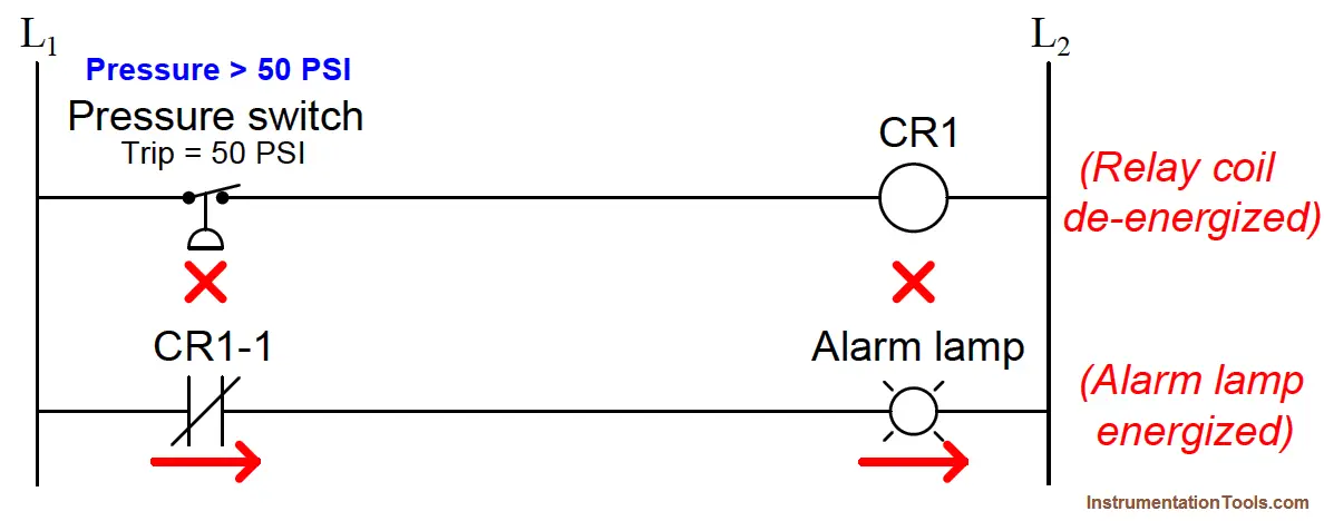 instrumentationtools.com
 ladder switch pressure logic diagram plc relays sensor effect hall tutorials principle animation working symbols actuated applied its instrumentationtools fluid
Solved Write A Program For The Relay Ladder Diagram Shown In | Chegg.com
 www.chegg.com
 ladder relay write program shown diagram figure solved problem normally given four question answer computer control three need these been
Solved Convert The Given Relay Ladder Diagram Into PLC | Chegg.com
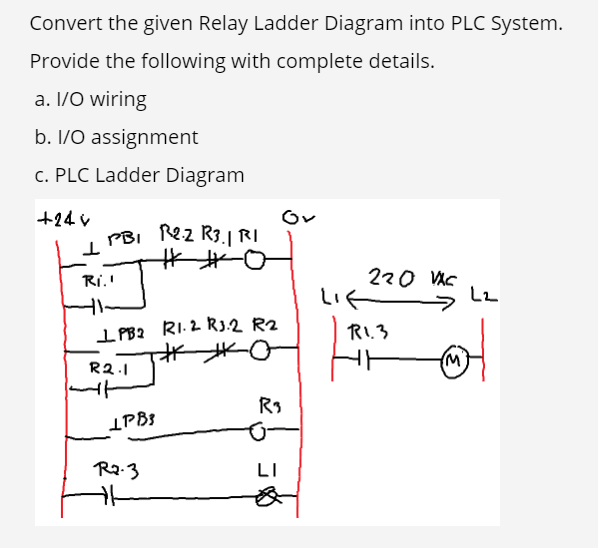 www.chegg.com
 ladder wiring
Relay Circuits And Ladder Diagrams | Relay Control Systems | Automation
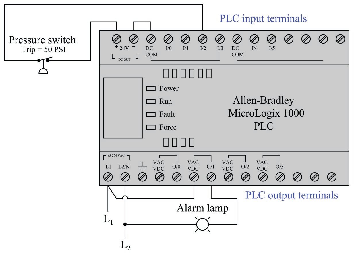 control.com
 ladder relay logic control diagram circuits wiring diagrams program
Relay Ladder Diagram (chapter 7) | Dinarimansari
 dinarimansari.wordpress.com
 ladder relay chapter diagram circuit bell fig control simple chap7 wordpress
Reverse Relay And Travel Limit Switch - PLC | Physics Forums
limit reverse relay switch plc travel ladder diagram switches advance guys thanks
Relay Circuits And Ladder Diagrams | Relay Control Systems | Automation
 control.com
 control relay ladder circuit switch light circuits alarm pressure diagrams contact activates where
Plc Ladder Diagram Examples - Boostermobi
diagram control pump wiring lag lead examples ladder plc float circuit level industrial edit logical sample
Solved Write A Program For The Relay Ladder Diagram Shown In | Chegg.com
 www.chegg.com
 ladder relay diagram program write shown figure transcribed text
The PLC Ladder Diagram. | Download Scientific Diagram
 www.researchgate.net
 ladder
Relay Circuits | Relay Circuit Diagram And Operation | Relay Schematic
 instrumentationtools.com
 relay schematic ladder symbols diagram circuits diagrams circuit contacts coils dashed between instrumentation instrumentationtools unlike association where represented associate lines
Ladder Diagrams - RoboticsUp
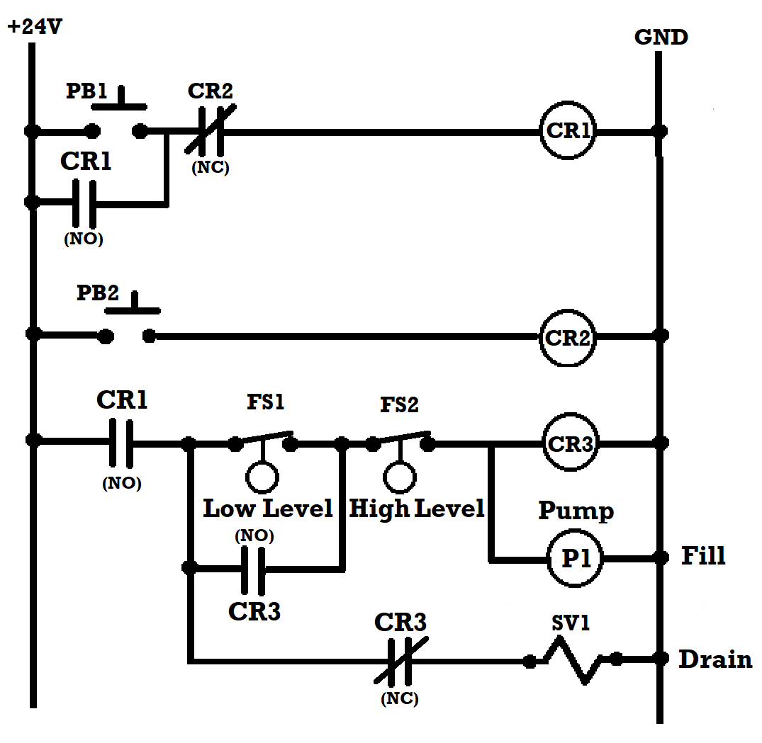 roboticsup.com
 diagrams relay programmable
Ladder Logic Wiring Diagrams - Wiring Diagram
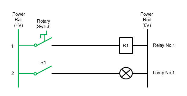 wiringdiagram.2bitboer.com
 ladder logic relay diagram wiring circuit example
Ladder Logic And Realy - HFO POWER PLANT
 hfoplant.blogspot.com
 ladder relay logic diagram realy controller simple
Relay4 « Engineering Expert Witness Blog
latching witness unlatching relay
How To Draw A Schematic Diagram ? - Inst Tools
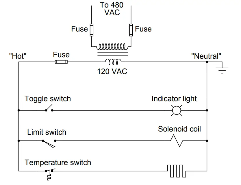 instrumentationtools.com
 diagram ladder schematic draw relay electrical switch diagrams example symbols instrumentationtools instrumentation symbolism same always while between
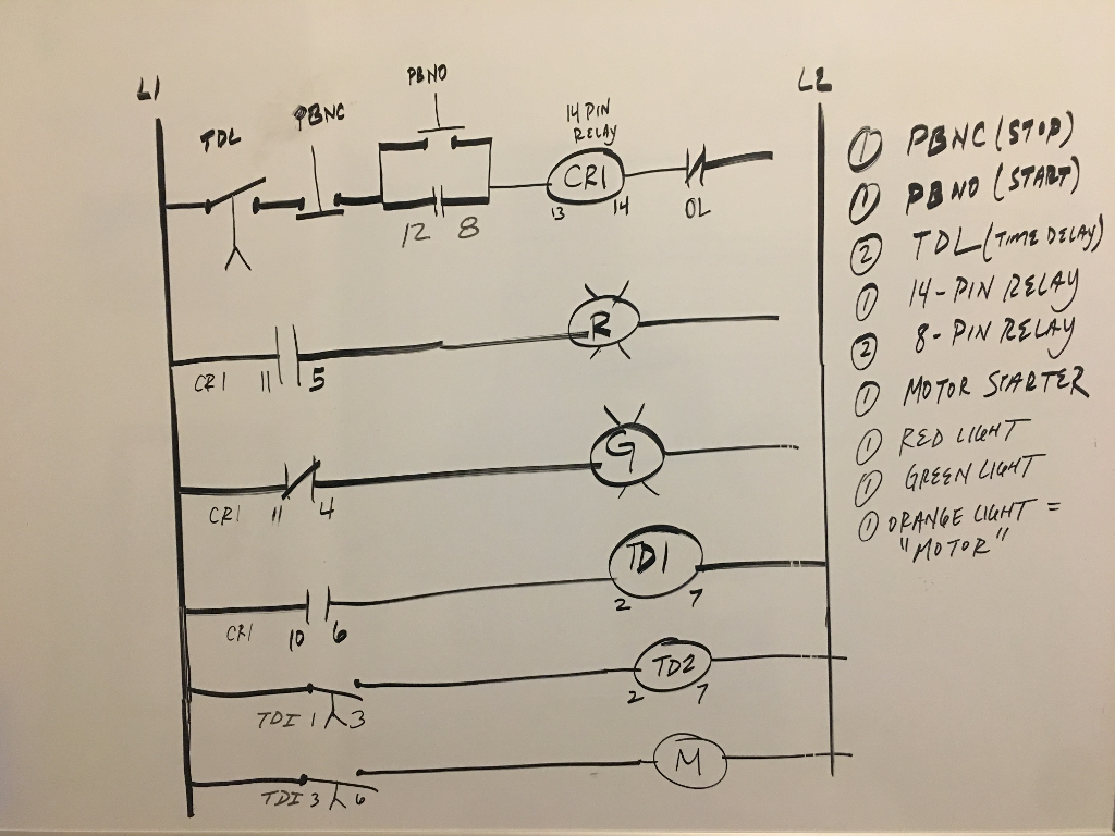
Wiring Diagram PDF: 14 Pin Relay Wiring Diagram
 wiring-pdf.blogspot.com
 ladder wiring pdf chegg pictorial
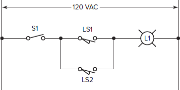
Solved: Write A Program For The Relay Ladder Diagram Shown In Figu
 www.chegg.com
 ladder relay write
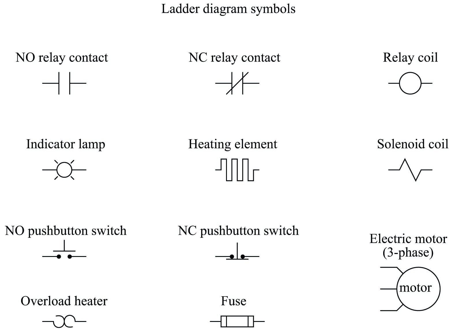
Relay Circuits And Ladder Diagrams | Relay Control Systems | Automation
 control.com
 relay ladder control diagrams circuits schematic pdf contacts automation coils
Relays In Ladder Logic Tutorials | Ladder Logic, Logic, Relay
 www.pinterest.com
 relay relays diagrams instrumentationtools electromechanical contactor symbology chart programming overload switches schematics coils
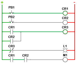
Ladder Logic Tutorial With Ladder Logic Symbols & Diagrams
 library.automationdirect.com
 ladder logic diagrams symbols diagram relay tutorial similarities understanding
Ladder Diagram | Schematic Diagram | Wiring Diagram | Electrical Academia
ladder diagram wiring diagrams electrical schematic circuit figure gif control
Panduan Ladder Diagram : Diagram Logika Relay - EDUKASIKINI.COM
 www.edukasikini.com
 relay logika panduan relai simbol sisi ditunjukkan kiri energi listrik literal fisik mencapai interpretasi melalui memberi untuk
15 Motor Control Ladder Diagram | Robhosking Diagram
Relay Circuits And Ladder Diagrams | Relay Control Systems | Automation
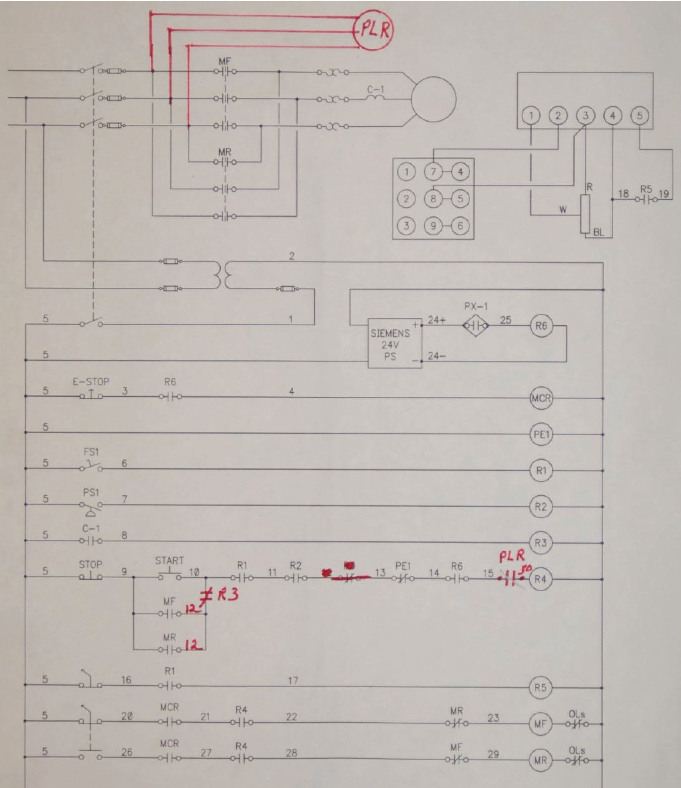 control.com
 control relay ladder circuits circuit diagram diagrams electrician modifications showing industrial made motor
Relay Logic Vs Ladder Logic - Ladder Logic World
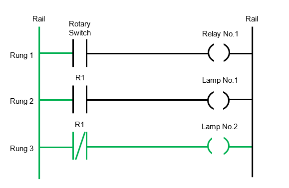 ladderlogicworld.com
 logic ladder relay diagram vs switch rotary
Ladder Diagram - Relay-Logic.com
 www.relay-logic.com
 Relay A & A2 Drop Out When Relay B Picks Up. (Ladder & Wiring Diagrams
 www.electriciantalk.com
 ladder relay wiring diagrams picks a2 included drop when
Solved: Write A Program For The Relay Ladder Diagram Shown... | Chegg.com
relay ladder diagram program write shown figure transcribed text show
Solved The Figure Shows A Relay Logic La Dder Diagram | Chegg.com
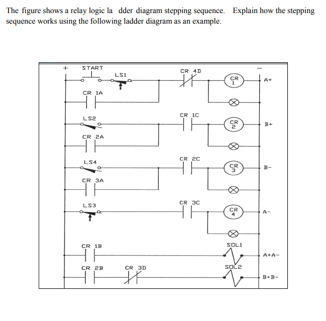 www.chegg.com
 relay logic sequence diagram dder shows figure la ladder stepping works using solved transcribed text problem been start following
Solved Write A Program For The Relay Ladder Diagram Shown In | Chegg.com
 www.chegg.com
 relay diagram program circuit ts ladder shown write solved problem
PLC Program For Mixing Tank | Mixing Process Using PLC Ladder Logic
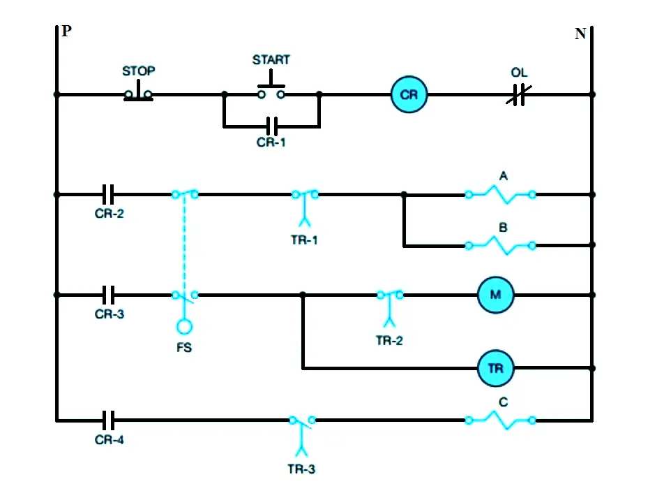 instrumentationtools.com
 plc mixing relay circuit logic ladder tank program process schematic fig instrumentationtools
Ladder relay chapter diagram circuit bell fig control simple chap7 wordpress. Diagram ladder schematic draw relay electrical switch diagrams example symbols instrumentationtools instrumentation symbolism same always while between. Solved write a program for the relay ladder diagram shown in